GMSH tutorial: how to draw a mesh over an image?
What is GMSH?
GMSH is an open-source tool commonly used to produce meshes of geometries in 2D or 3D. It is both a command line tool and a graphical user interface.
Drawing a mesh on top of an image
An interesting feature of the graphical user interface is that it can display images as a background to the interactive drawing. According to the documentation, it is possible to include images in JPEG, PNG or PDF format.
Searching on the internet, I have found a starting point for this tutorial in this post from 2014: http://onelab.info/pipermail/gmsh/2014/009289.html
However, I find the post hard to follow and had to make up my own understanding. The document this, I’ll try to explain a few of the options GMSH offers with associated screenshots in this tutorial.
Writing a mesh.geo file with a background image (version 1)
If you have an image you want to draw on top, start by creating new mesh.geo file with the following lines.
General.BackgroundImageFileName = "background_image.jpg";
General.BackgroundImage3D = 0; // 2D bg image (if set to 1, will draw in 3D model coordinates)
General.BackgroundImagePositionX = 10; // in pixels (or in model units in 3D case)
General.BackgroundImagePositionY = 10;
General.BackgroundImageWidth = -1; // actual size
General.BackgroundImageHeight = -1; // actual size
Once the file has been saved, you can now open it in the GMSH GUI by typing the following at the command line.
gmsh mesh.geo
Once in the main screen, you should now see your image.
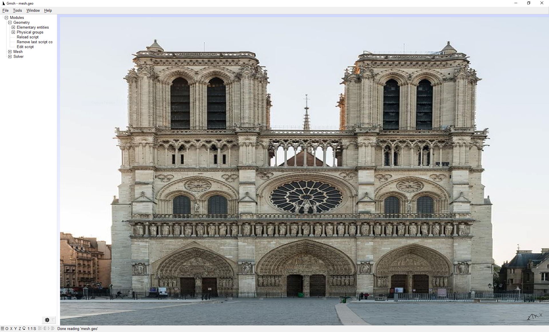
Writing a mesh.geo file with a background image (version 2)
As you may have noticed in the previous image, the background image is distorted by as it has been automatically adjusted to the width of the GMSH application window. It is possible to modify this behaviour by adjusting the script.
General.BackgroundImageFileName = "background_image.jpg";
General.BackgroundImage3D = 0; // 2D bg image (if set to 1, will draw in 3D model coordinates)
General.BackgroundImagePositionX = 1e5; // centered
General.BackgroundImagePositionY = 1e5; // centered
General.BackgroundImageWidth = 0; // don’t stretch
General.BackgroundImageHeight = 0; // don’t stretch
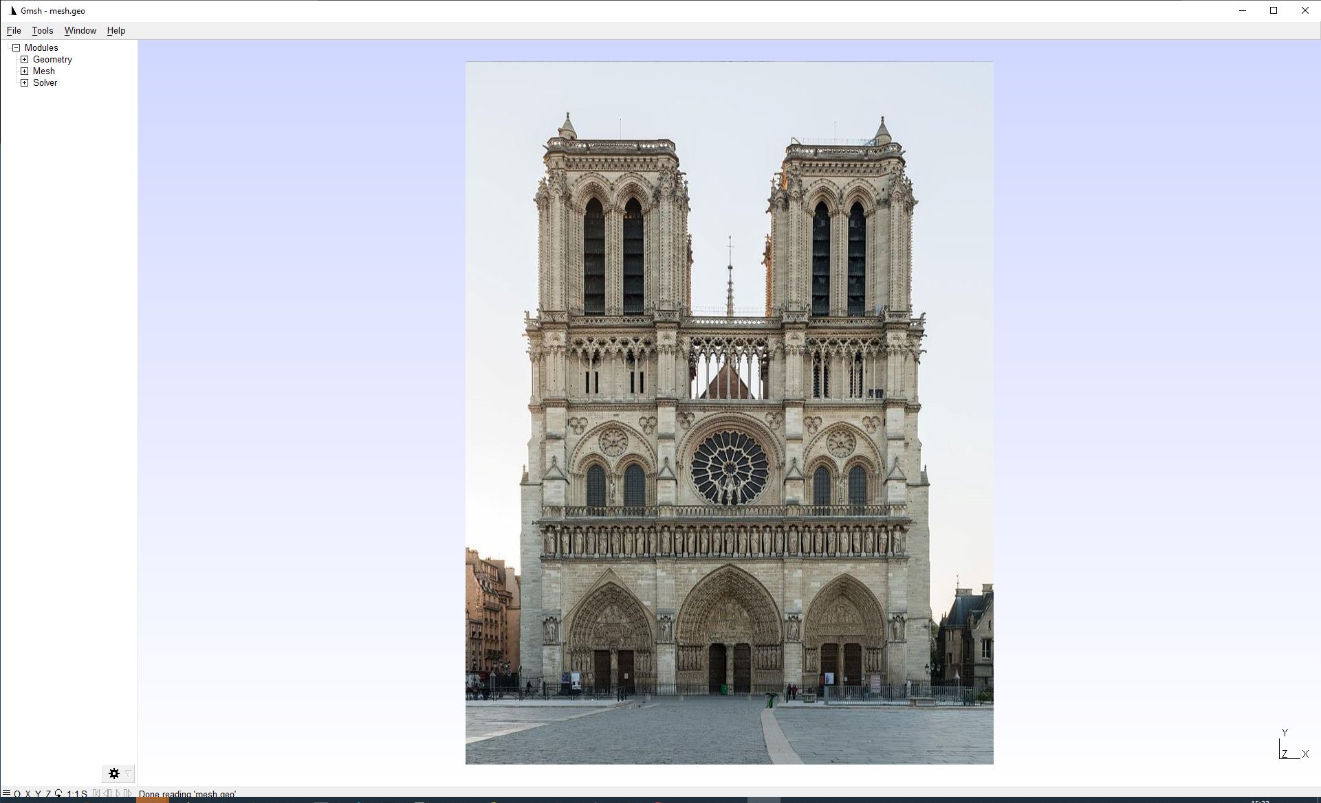
Drawing a rectangular boundary before adding points
One thing I have noticed is that GMSH automatically resizes the zooming of the image once you add points.
The workaround I found is to draw a rectangular window which can be easily adapted
the background image. To do this, we can add the following code to mesh.geo
(depending on the size of your image, you will have to change the image_width and height variables):
image_width = 768;
image_height = 1024;

// border points
Point(1) = {-image_width/2., -image_height/2., 0, 1.0};
Point(2) = {image_width/2., -image_height/2., 0, 1.0};
Point(3) = {image_width/2., image_height/2., 0, 1.0};
Point(4) = {-image_width/2., image_height/2., 0, 1.0};

// outer contour
Line(1) = {1, 2};
Line(2) = {2, 3};
Line(3) = {3, 4};
Line(4) = {4, 1};
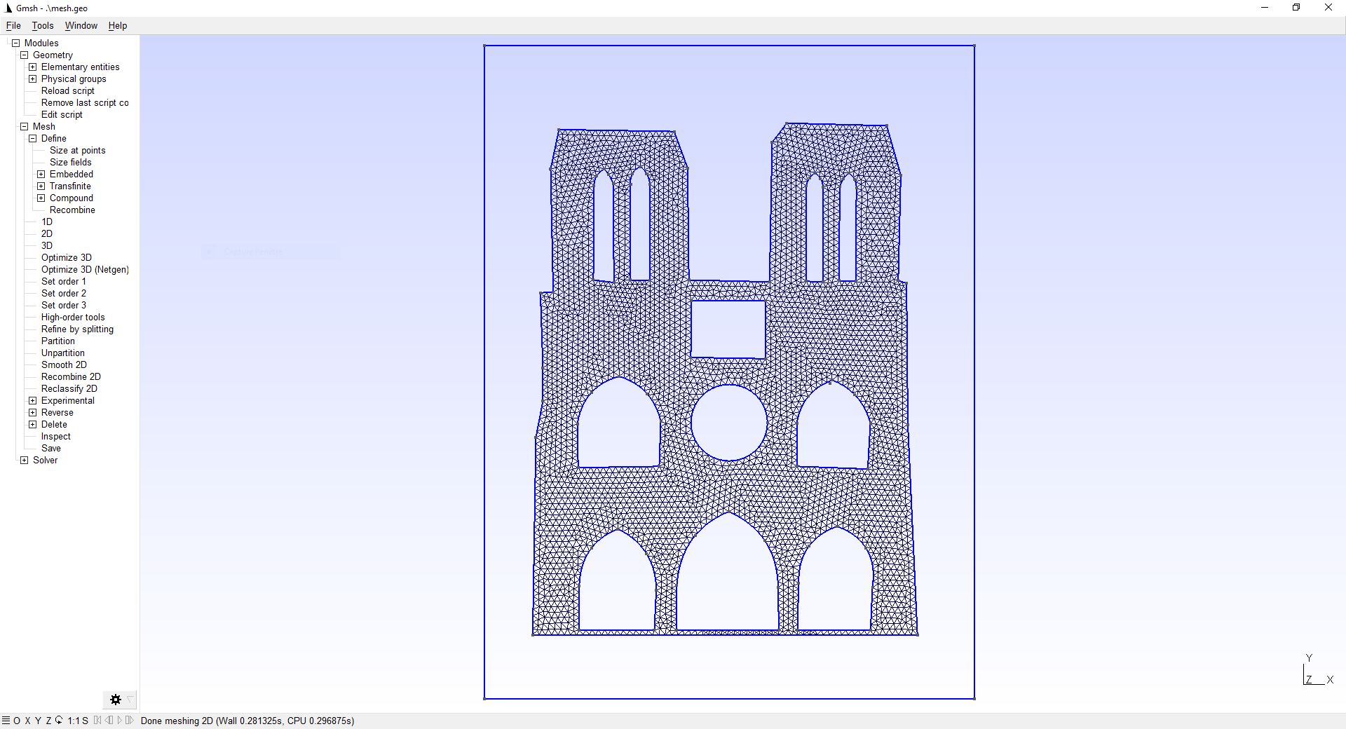
Once we have done this, we get the following:
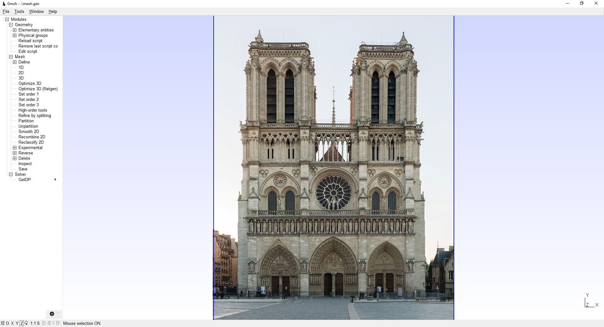
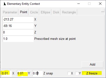
We can now draw the usual primitives (points, lines, etc.) on top and create a mesh of our background image. An important options is to adjust the snapping to a value that makes sense for your image, since the points snap to an imaginary grid that uses the resolution shown in the window below.
Final model and finite element computation
If everything goes well, you should be able to master the meshing process and obtain something like this:
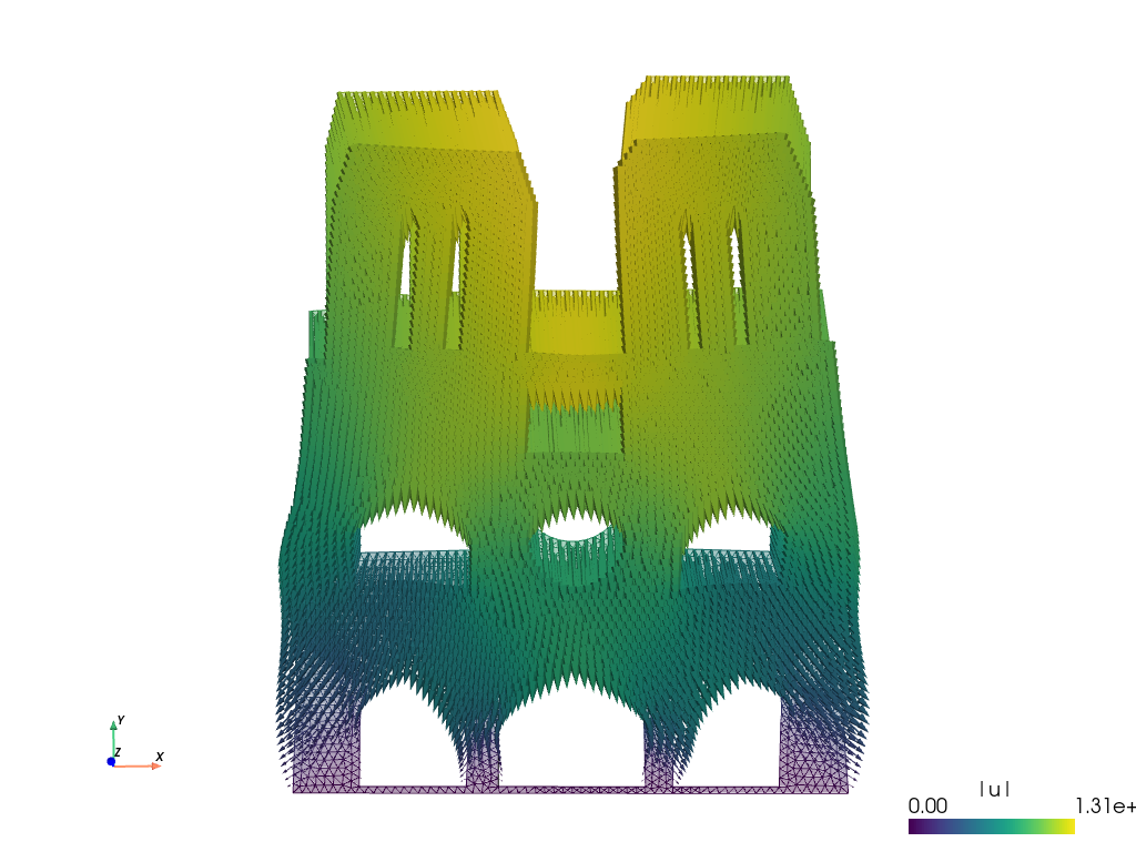
This mesh can then be used with a finite element toolkit like Sfepy (but there are many others like Fenics, Freefem or Gridap) to solve a static elasticity problem.
Downloads
The mesh.geo file can be downloaded here: mesh.geo.
The mesh.vtk file can be downloaded here: mesh.vtk.
The sfepy script can be downloaded here: notre_dame.py


